 Small Technical Blog
Coreboot on ThinkPad W500
Goal:
Give an old Lenovo Thinkpad W500 a second life featuring Coreboot and Ubuntu
My partner replaced his laptop already two years and half ago, buying a beautiful brand-new Lenovo Thinkpad T480s. The old machine, a Lenovo Thinkpad W500 - heavier and bulkier and a lot less pretty - wasn’t getting any further updates for Windows 7 and it was painfully slow, rarely being used. Furthermore, the machine was overheating and the battery was almost dead.
I got permission to play around with this old machine - even after pointing out the risks - and to try to give it a second life:
- Replacing the propietary firmware with a self-built Coreboot, since Thinkpads are usually good supported
- Installing the latest Ubuntu LTS Desktop version
- Using the laptop plugged in only (and maybe getting a new battery)
NOTE: the risks are a) bricking the machine b) breaking something during disassembling
- The mainboard vendor and the mainboard model must be supported by Coreboot
- To have a SPI flasher
- To have a SPI pin clip
- Find out the ROM size
- Make a bootable Live Ubuntu USB stick
Googling a little around I found that the W500 was almost identical to the T400, which was listed on the list of boards officially supported by coreboot. I also found the blogs of two guys which managed to install libreboot on the same laptop.
I own a SPI flasher (from the time I flashed Coreboot to my librem and I needed to have a brick-contingency plan).
The flash chip on the mainboard of my W500 has 8 pins. I had a SPI 8-pin clip.
NOTE: in the blogs I mentioned before, the referenced mainboards featured a 16-pin chip. Since they were playing with exactly the same laptop than me, I thought that would be the case for me as well. So I ordered a 16-pin clip and let the project on hold, mainly waiting for the clip to arrive. Funny fact I discovered only after dissasembling: my mainboard had a 8-pin chip!
After booting from the Live Ubuntu USB drive, run the following to find out the ROM size:
ubuntu@ubuntu:~$ dmidecode | grep ROM\ Size
        ROM Size: 4096 kB
Before dissasembling the machine, find out what can be done accessing the chip internally i.e. which read/write permissions the different regions have.
Re-boot with the Live Ubuntu USB stick.
Important: when the live CD is starting, press TAB. Modify the boot options to add nopat and iomem=relaxed.
After booting, verify that both options were correctly set:
ubuntu@ubuntu:~/ cat /proc/cmdline
... iomem=relaxed nopat ...
Install flashrom. Flashrom is not available for ubuntu as a package - it must be built first. Install git and build dependencies:
ubuntu@ubuntu:~/flashrom$ sudo apt-get install git build-essential libpci-dev libusb-1.0
Clone flashrom repository, compile and make executable:
ubuntu@ubuntu:~/ git clone https://review.coreboot.org/flashrom.git
ubuntu@ubuntu:~/ cd flashrom
ubuntu@ubuntu:~/flashrom$ make
ubuntu@ubuntu:~/flashrom$ sudo cp flashrom /usr/local/bin/
ubuntu@ubuntu:~/flashrom$ sudo chmod +x /usr/local/bin/flashrom
Try to access the chip internally using flashrom:
ubuntu@ubuntu:~/w500$ sudo ./flashrom -p internal
flashrom v1.2-167-g6cdde54 on Linux 5.4.0-26-generic (x86_64)
flashrom is free software, get the source code at https://flashrom.org

Using clock_gettime for delay loops (clk_id: 1, resolution: 1ns).
Found chipset "Intel ICH9M".
Enabling flash write... SPI Configuration is locked down.
FREG0: Flash Descriptor region (0x00000000-0x00000fff) is read-only.
FREG2: Management Engine region (0x00001000-0x001f5fff) is locked.
Not all flash regions are freely accessible by flashrom. This is most likely
due to an active ME. Please see https://flashrom.org/ME for details.
PR0: Warning: 0x003e0000-0x01ffffff is read-only.
At least some flash regions are read protected. You have to use a flash
layout and include only accessible regions. For write operations, you'll
additionally need the --noverify-all switch. See manpage for more details.
OK.
Found Macronix flash chip "MX25L3205(A)" (4096 kB, SPI) mapped at physical address 0x00000000ffc00000.
Found Macronix flash chip "MX25L3205D/MX25L3208D" (4096 kB, SPI) mapped at physical address 0x00000000ffc00000.
Found Macronix flash chip "MX25L3206E/MX25L3208E" (4096 kB, SPI) mapped at physical address 0x00000000ffc00000.
Found Macronix flash chip "MX25L3273E" (4096 kB, SPI) mapped at physical address 0x00000000ffc00000.
Multiple flash chip definitions match the detected chip(s): "MX25L3205(A)", "MX25L3205D/MX25L3208D", "MX25L3206E/MX25L3208E", "MX25L3273E"
Please specify which chip definition to use with the -c <chipname> option.
Basing on the output:
- There are different chip definitions matching the detected chip, to find out which one is ours we’ll need to take a look at the chip itself after disassembling
- The descriptor region is read-only
- The management engine region is locked
- The bios should be enabled for reading and writting - since the contrary was not stated
According to the last point, it is possible to make a backup of the original bios region without diassembling.
NOTE: actually to do so we need to know the exact chip definition, what we theoretically do not know before proceeding with the disassembling. For that I relied on the information I found in other blog posts. See references.
So I read the bios region:
ubuntu@ubuntu:~/w500$ sudo ./flashrom --ifd -c "MX25L3205D/MX25L3208D" -p internal -i bios -r bios_orig.rom
flashrom v1.2-167-g6cdde54 on Linux 5.4.0-26-generic (x86_64)
flashrom is free software, get the source code at https://flashrom.org

Using clock_gettime for delay loops (clk_id: 1, resolution: 1ns).
Found chipset "Intel ICH9M".
Enabling flash write... SPI Configuration is locked down.
FREG0: Flash Descriptor region (0x00000000-0x00000fff) is read-only.
FREG2: Management Engine region (0x00001000-0x001f5fff) is locked.
Not all flash regions are freely accessible by flashrom. This is most likely
due to an active ME. Please see https://flashrom.org/ME for details.
PR0: Warning: 0x003e0000-0x01ffffff is read-only.
At least some flash regions are read protected. You have to use a flash
layout and include only accessible regions. For write operations, you'll
additionally need the --noverify-all switch. See manpage for more details.
OK.
Found Macronix flash chip "MX25L3205D/MX25L3208D" (4096 kB, SPI) mapped at physical address 0x00000000ffc00000.
Reading ich descriptor... done.
Using region: "bios".
Reading flash... done.
A couple of clarifications about this command:
- The parameter –ifd allows using the flash descriptor on the chip to read or write regions on the chip
- The parameter -c indicates the chip to be used
- The parameter -p with value internal says to access the chip on the machine internally
- The parameter -i says which region to access - in this example is the bios (i.e. the region where coreboot must be flashed)
- The parameter -r says to read the desired region to the given file
Now we had a backup of the original bios (without flash descriptor and without ME) on the binary file bios_orig.rom.
I stored it safelly away (GoogleDocs), since it might be useful for a recovery action with the flasher, in case of a brick.
This was for me the scariest part. Even if I had a SPI flasher, I had never used it before. Reading the rom and flashing coreboot on the Librem is possible without having to disassemble the machine. And I had never bricked it (fingers crossed), so I have never needed the flasher. However most chips don’t allow to flash a new firmware through the internal programmer, so I had to disassemble:
- to read the complete existing rom (including bios, flash descriptor, ME and Gbe)
- to flash coreboot for the first time
NOTE: after flashing coreboot manually for the first time, we remove the write protection, so subsequent flashings can be performed directly through the internal programmer.
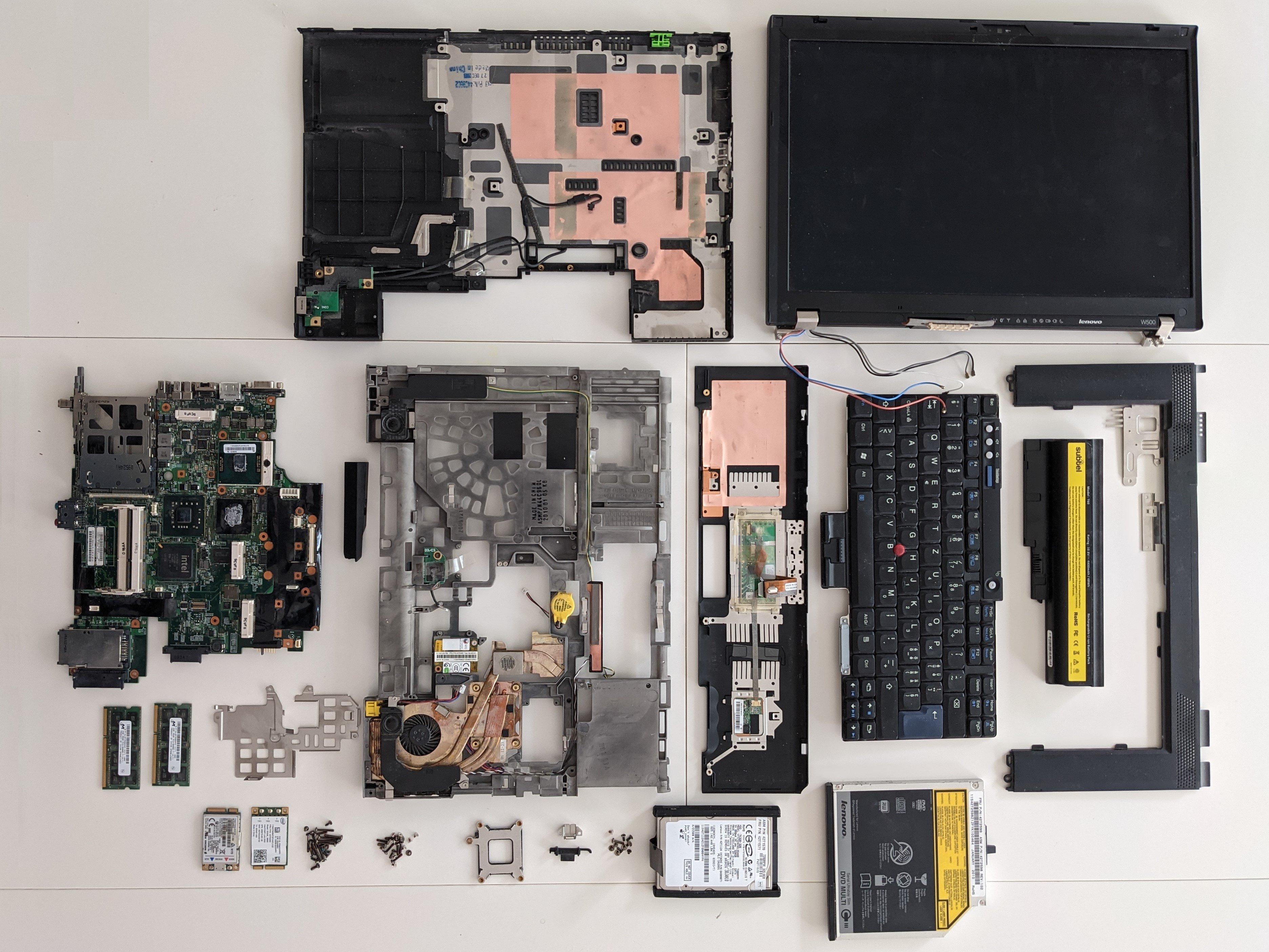
First surprise: it was way worst than I have thought. The ROM chip on the Thinkpad W500 is really hidden, meaning you need to disassemble the PC completely in order to access it.
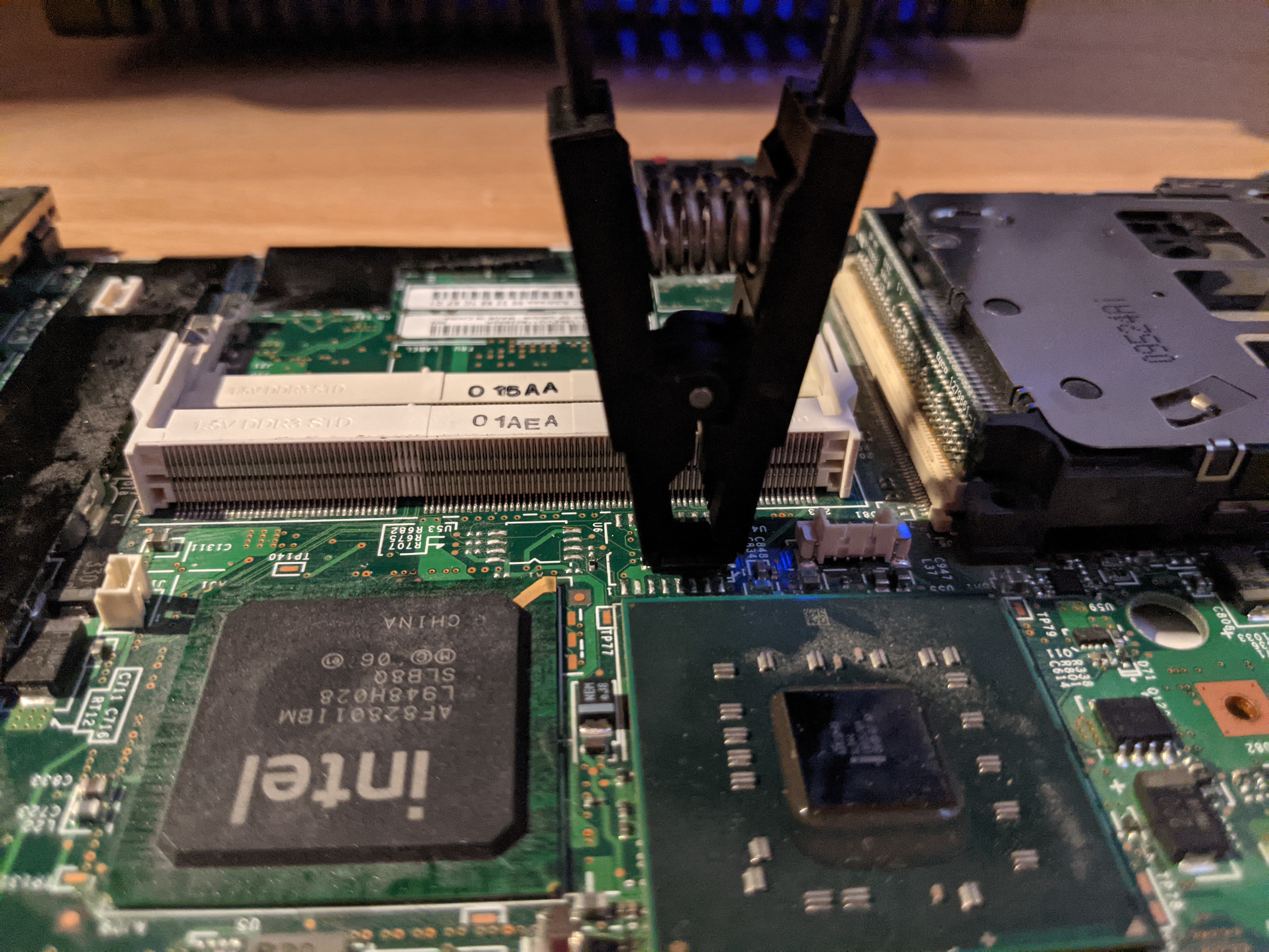
Disassembling took long, but one day the little chip finally saw the sunlight. I took a zoomed picture to confirm the chip name.
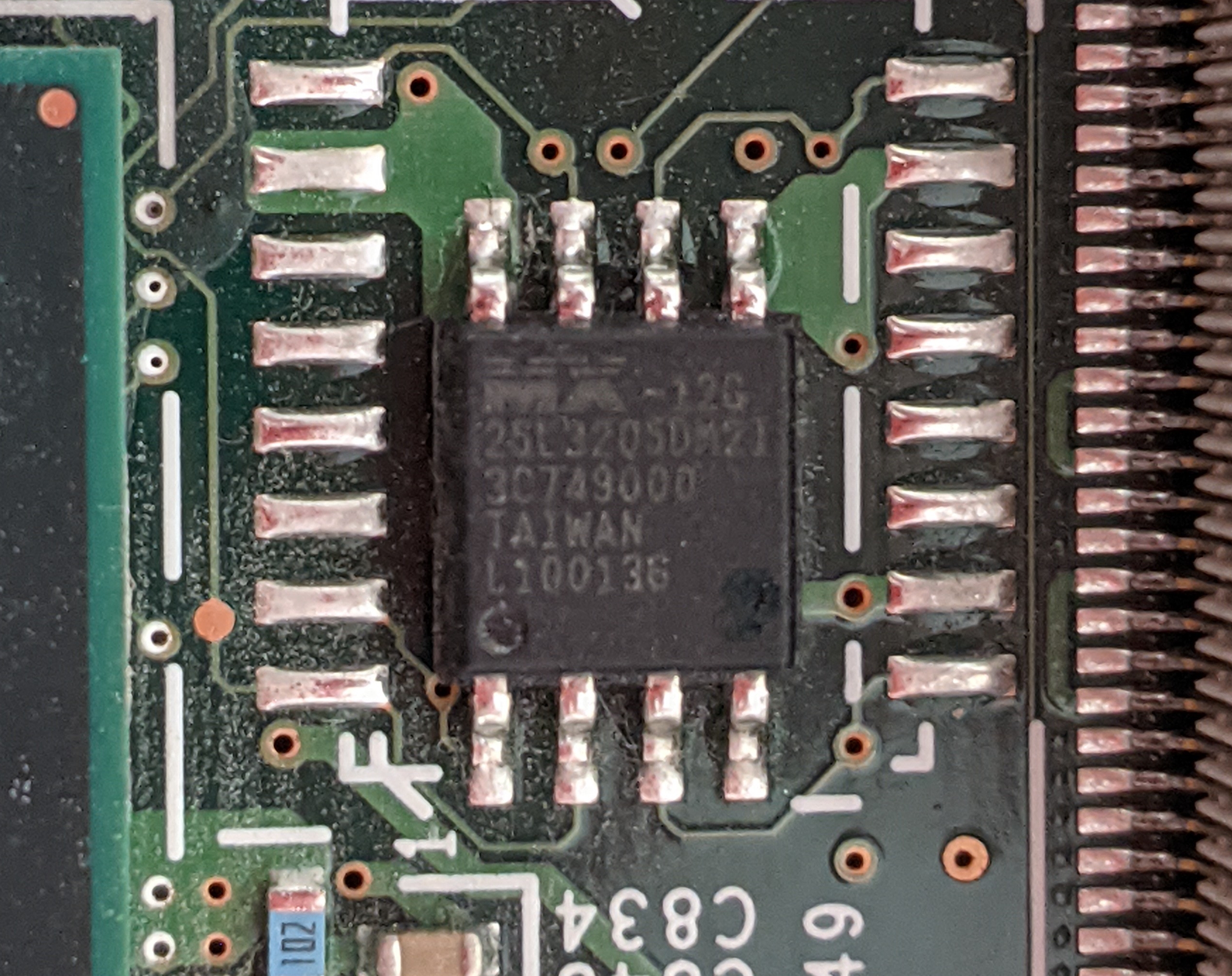
Second suprise: the chip had 8 pins and not 16 as I had expected! Apparently identical laptops might have different ROM chips.
In the picture we are able to read MX25L3205DMi-12G, which matches the one we selected before for the internal partial bios read.
Surfing the web I found the specifications with a beautiful pin diagram looking like this:
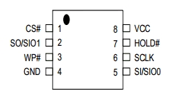
Almost all ROM chips follow the same pin disposition. Important thing is to locate pin number 1:
- On the chip, finding out the little circle graved in the chip surface, which always indicates pin number 1
- On the clip and cable, indicated by the red wire
- On the programmer
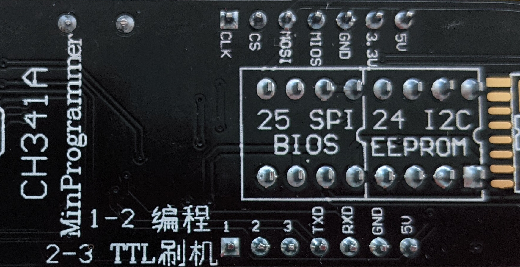
The SPI programmer includes a diagram on the back side which a picture of the chip (25 SPI BIOS) and a half circle which marks the top. Now you have to think that you are looking at the chip from below: the pin number 1 is therefore the fourth from left to right, on the lower row.
So with this information we get an idea about how to connect the clip to the programmer and the clip to the chip. The clip attached to the programmer looked like this:
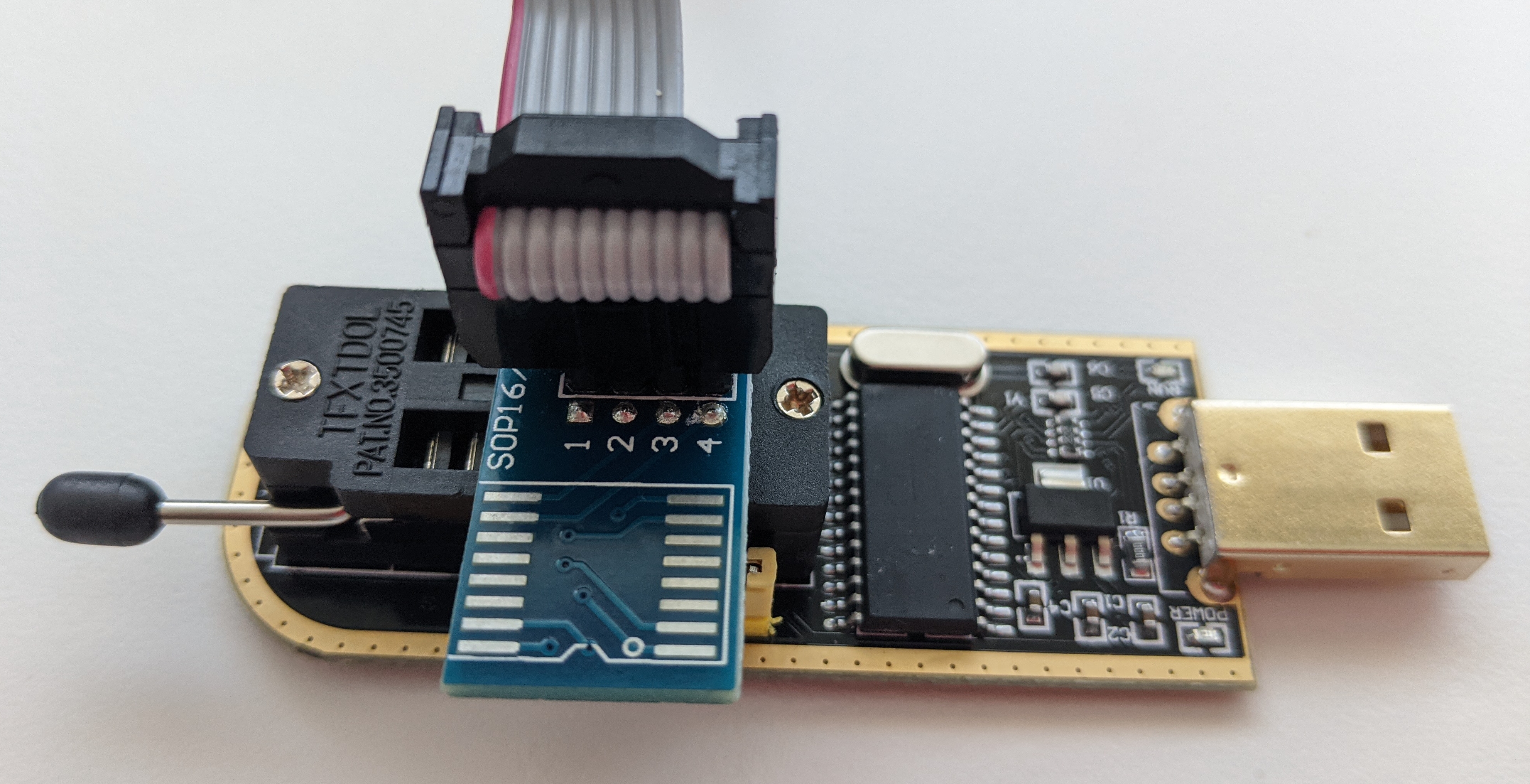
Now if you manage to flip the programmer from right to left in your mind - looking now from above - you’ll see on the picture the pin number one matches the red wire.
Since I needed several attempts to make this work and the information might be useful to others, I’m including the failed attempts and the reasons behind them in this section. If not interested, just skip to 2.4. Success!.
If not installed yet, install flashrom:
eramon@caipirinha:~/dev/thinkpadw500$ sudo apt-get install flashrom
Now connect the clip to the chip, taking care of having the red wire connected to pin number 1, as explained in the last section.
First try: executing flashrom with just the programmer parameter should return a list of the chip specifications matching the detected chip. Well, that did not happen:
eramon@caipirinha:~/dev/thinkpadw500$ sudo flashrom --programmer ch341a_spi
flashrom v1.2 on Linux 5.6.0-2-amd64 (x86_64)
flashrom is free software, get the source code at https://flashrom.org

Using clock_gettime for delay loops (clk_id: 1, resolution: 1ns).
Couldn't open device 1a86:5512.
Error: Programmer initialization failed.
The problem was that I have removed the jumper from the programmer, which binds the two most external pins on the upper side together. Don’t remove it or otherwise the spi programmer won’t be able to read the chip! How did I find out? As soon as I decided to try with another SPI programmer - I had two of them - and saw the same jumper I had removed in the same place.
NOTE: first I thought the problem was my laptop i.e. the kernel module ch341 preventing the programmer to work correctly. I added “blacklist ch341” to /etc/modprobe.d/ch341.conf and removed the module manually with rmmod, which prevented the module from loading. However, after retrying the flashrom command I saw no difference whatsoever, so that wasn’t the problem. At least not the only one.
With the jumper on, I tried again, this time I got another error:
eramon@caipirinha:~/dev/thinkpadw500$ sudo flashrom -p ch341a_spi
flashrom v1.2-230-gc193fbd on Linux 5.6.0-2-amd64 (x86_64)
flashrom is free software, get the source code at https://flashrom.org

Using clock_gettime for delay loops (clk_id: 1, resolution: 1ns).
No EEPROM/flash device found.
Note: flashrom can never write if the flash chip isn't found automatically.
At this point, I tried and re-tried and checked the wiring and the grasp of the clip - alternating both spi programmers - but nothing was working. I thought I had broken the chip during trying. Just before giving up, I decided to start with a working scenario and move progressively towards the setup I needed.
To set up this initial working situation, I was going to read the rom chip from my - productive - laptop, the Librem13v1. I found the specifications of the chip and saw that the pin distribution was the same as the one for the W500 chip. So I removed the back of the laptop. Luckily, on the Librem the rom chip is easily accessible with just removing the back side - 12 screws only!
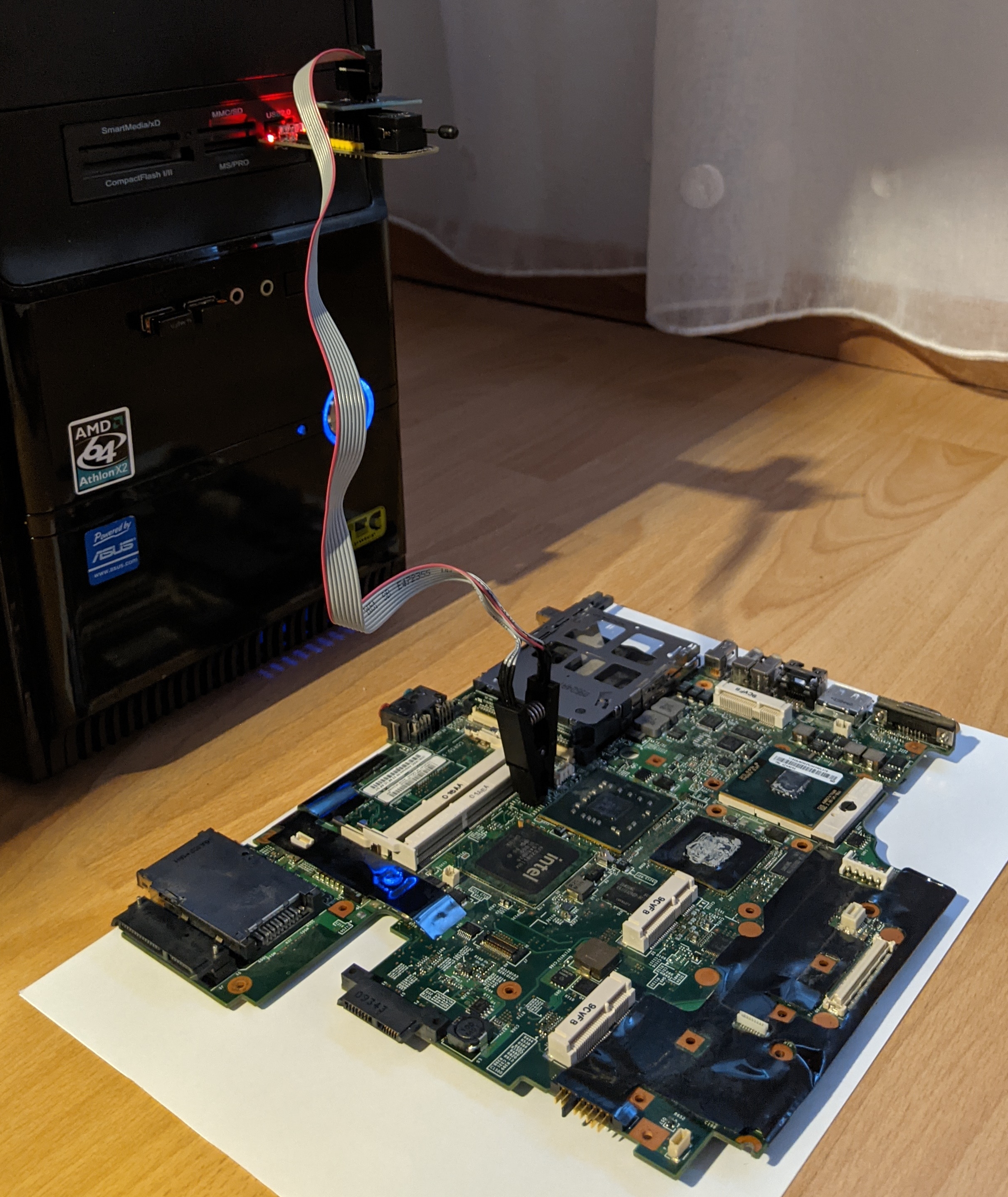
I installed flashrom on my old desktop PC running Ubuntu (since the flashrom I was using before was the one on the laptop whose chip I was trying to read). I connected the clip to the chip, exactly as before, inserted the programmer in the PC and ran the same flashrom command:
eramon@whisky:~$ sudo flashrom -p ch341a_spi
flashrom v1.2-230-gc193fbd on Linux 5.4.0-58-generic (x86_64)
flashrom is free software, get the source code at https://flashrom.org

Using clock_gettime for delay loops (clk_id: 1, resolution: 1ns).
Found Macronix flash chip "MX25L6405" (8192 kB, SPI) on ch341a_spi.
Found Macronix flash chip "MX25L6405D" (8192 kB, SPI) on ch341a_spi.
Found Macronix flash chip "MX25L6406E/MX25L6408E" (8192 kB, SPI) on ch341a_spi.
Found Macronix flash chip "MX25L6436E/MX25L6445E/MX25L6465E/MX25L6473E/MX25L6473F" (8192 kB, SPI) on ch341a_spi.
Multiple flash chip definitions match the detected chip(s): "MX25L6405", "MX25L6405D", "MX25L6406E/MX25L6408E", "MX25L6436E/MX25L6445E/MX25L6465E/MX25L6473E/MX25L6473F"
Please specify which chip definition to use with the -c <chipname> option.
So the programmer was working correctly, the wiring was right and flashrom on the ubuntu PC were working correctly. Next step would be to try the same setup changing the clip to the w500 board.
Connecting the clip to the chip on the w500 motherboard and the spi programmer to the ubuntu PC in the same way I just did with the librem, I tried again:
eramon@whisky:~$ sudo flashrom -p ch341a_spi
[sudo] password for eramon:
flashrom v1.2-230-gc193fbd on Linux 5.4.0-58-generic (x86_64)
flashrom is free software, get the source code at https://flashrom.org

Using clock_gettime for delay loops (clk_id: 1, resolution: 1ns).
Found Macronix flash chip "MX25L3205(A)" (4096 kB, SPI) on ch341a_spi.
Found Macronix flash chip "MX25L3205D/MX25L3208D" (4096 kB, SPI) on ch341a_spi.
Found Macronix flash chip "MX25L3206E/MX25L3208E" (4096 kB, SPI) on ch341a_spi.
Found Macronix flash chip "MX25L3273E" (4096 kB, SPI) on ch341a_spi.
Multiple flash chip definitions match the detected chip(s): "MX25L3205(A)", "MX25L3205D/MX25L3208D", "MX25L3206E/MX25L3208E", "MX25L3273E"
Please specify which chip definition to use with the -c <chipname> option.
This time it worked! The programmer was able to read the rom and found several matching chip definitions, among them “MX25L3205D/MX25L3208D”, which was the expected one.
I re-assembled my Librem again, putting in place all its 12 little screws. I booted and after some more re-tries with flashrom and the programmer I was able to obtain the same result as with the ubuntu PC. Apparently one of the USB ports on the laptop had an issue. In addition the grasp of the clip on the chip wasn’t very good. All these things together made the initial try and error difficult. But now I was able to read the chip using flashrom on either of the two machines.
NOTE: one thing which would have helped if I had known is that both little red leds on the programmer, at either sides of the USB connector, must be lighting. If not, the connection is not good.
Run flashrom to backup the existing firmware (bios):
eramon@whisky:~$ sudo flashrom -p ch341a_spi -c MX25L3205D/MX25L3208D -r w500_1.rom
flashrom v1.2-230-gc193fbd on Linux 5.4.0-58-generic (x86_64)
flashrom is free software, get the source code at https://flashrom.org

Using clock_gettime for delay loops (clk_id: 1, resolution: 1ns).
Found Macronix flash chip "MX25L3205D/MX25L3208D" (4096 kB, SPI) on ch341a_spi.
Reading flash... done.
Do it twice, so we can compare the image checksums afterwards:
eramon@whisky:~$ sudo flashrom -p ch341a_spi -c MX25L3205D/MX25L3208D -r w500_2.rom
flashrom v1.2-230-gc193fbd on Linux 5.4.0-58-generic (x86_64)
flashrom is free software, get the source code at https://flashrom.org

Using clock_gettime for delay loops (clk_id: 1, resolution: 1ns).
Found Macronix flash chip "MX25L3205D/MX25L3208D" (4096 kB, SPI) on ch341a_spi.
Reading flash... done.
Make sure the image is not corrupt, comparing the checksum of both results:
eramon@whisky:~$ sha1sum w500*.rom
f3e162e9400f63d36fc7d9f7e003542be874cec5  w500_1.rom
f3e162e9400f63d36fc7d9f7e003542be874cec5  w500_2.rom
Looking good so far.
I mainly followed the instructions on the coreboot documentation.
NOTE: I already had the build dependencies installed on my laptop. See previous blog post “Build Coreboot”.
The libraries and tools needed to build coreboot were already installed on my laptop.
Pull the latest version of coreboot and update submodules:
eramon@caipirinha:~/dev/thinkpadw500$ git clone https://review.coreboot.org/coreboot
eramon@caipirinha:~/dev/thinkpadw500$ cd coreboot
eramon@caipirinha:~/dev/thinkpadw500$ git submodule update --init --checkout
The last step checks out a subrepository on the 3rdparty directory.
Build the cross-compiler (all architectures):
eramon@caipirinha:~/dev/thinkpadw500/coreboot$ make crossgcc CPUS=4

Building toolchain using 4 thread(s).
Target architecture is i386-elf
Build ifdtool:
eramon@caipirinha:~/dev/thinkpadw500/coreboot$ cd util
eramon@caipirinha:~/dev/thinkpadw500/coreboot/util/ifdtool$ make
eramon@caipirinha:~/dev/thinkpadw500/coreboot/util/ifdtool$ cd ..
idftool is a program to extract and dump Intel Firmware Descriptor information.
As a payload I’ll use SeaBIOS, which:
- is the default payload downloaded and built during the coreboot build process
- supports booting of ubuntu and other linux distributions in bios mode
According to the documentation, for Intel boards following files must be provided since coreboot can’t generate them itself:
- Intel Flash Descriptor region (descriptor.bin)
- Intel Gigabit Ethernet firmware (gbe.bin)
- Intel Management Engine (me.bin)
Use ifdtool to extract the flash regions from the rom image:
eramon@caipirinha:~/dev/thinkpadw500/coreboot$ sudo ./util/ifdtool/ifdtool -x ../w500_1.rom
[sudo] password for eramon:
File ../w500_1.rom is 4194304 bytes
  Flash Region 0 (Flash Descriptor): 00000000 - 00000fff
  Flash Region 1 (BIOS): 00200000 - 003fffff
  Flash Region 2 (Intel ME): 00001000 - 001f5fff
  Flash Region 3 (GbE): 001f6000 - 001f7fff
  Flash Region 4 (Platform Data): 001f8000 - 001fffff
Idftool extracts the different flash regions to binary files:
eramon@caipirinha:~/dev/thinkpadw500/coreboot$ ls -la *.bin
-rw-r--r-- 1 root root    4096 Apr 28 12:13 flashregion_0_flashdescriptor.bin
-rw-r--r-- 1 root root 2097152 Apr 28 12:13 flashregion_1_bios.bin
-rw-r--r-- 1 root root 2052096 Apr 28 12:13 flashregion_2_intel_me.bin
-rw-r--r-- 1 root root    8192 Apr 28 12:13 flashregion_3_gbe.bin
-rw-r--r-- 1 root root   32768 Apr 28 12:13 flashregion_4_platform_data.bin
Once the sources, tools and binaries are available, configure build-time options of coreboot.
eramon@caipirinha:~/dev/thinkpadw500/coreboot$ make menuconfig
We need to tell the compiler where to find the binary blobs:
-
On the Mainboard menu, as vendor select Lenovo
-
On the Mainboard menu, as model select Thinkpad W500
-
On the Mainboard menu, as ROM chip size, select 4096 KB (4 MB))
-
On the Chipset menu, verify that Protect flash regions -> Unlock flash regions is selected
-
On the Chipset menu, Add Intel descriptor.bin file: YES
-
On the Chipset menu, Add Intel ME/TXE Firmware: YES
-
On the Chipset menu, Add gigabit ethernet configuration: YES
-
On the Chipset menu, Allows HOST/CPU read access to ME region: YES
-
On the Payload menu, make sure that SeaBIOS is selected
Save and exit. The configuration is saved to .config
Under the Chipset menu, we just saw where the binary files must be located:
3rdparty/blobs/mainboard/$(MAINBOARDDIR)/descriptor.bin
3rdparty/blobs/mainboard/$(MAINBOARDDIR)/me.bin
3rdparty/blobs/mainboard/$(MAINBOARDDIR)/gbe.bin
The value of $(MAINBOARDDIR) could be find in the .config file:
CONFIG_MAINBOARD_DIR="lenovo/t400"
Create the directory and copy the files to the right location:
eramon@caipirinha:~/dev/thinkpadw500/coreboot$ mkdir -p 3rdparty/blobs/mainboard/lenovo/t400
eramon@caipirinha:~/dev/thinkpadw500/coreboot$ cp flashregion_0_flashdescriptor.bin 3rdparty/blobs/mainboard/lenovo/t400/descriptor.bin
eramon@caipirinha:~/dev/thinkpadw500/coreboot$ cp flashregion_2_intel_me.bin 3rdparty/blobs/mainboard/lenovo/t400/me.bin
eramon@caipirinha:~/dev/thinkpadw500/coreboot$ cp flashregion_3_gbe.bin 3rdparty/blobs/mainboard/lenovo/t400/gbe.bin
Build coreboot:
eramon@caipirinha:~/dev/thinkpadw500/coreboot$ make
After successfully build we had the image ready to be flashed:
eramon@caipirinha:~/dev/thinkpadw500/coreboot$ ls -la build/coreboot.rom
-rw-r--r-- 1 eramon eramon 4194304 Apr 28 13:15 build/coreboot.rom
Flash coreboot:
eramon@caipirinha:~/dev/thinkpadw500/coreboot$ sudo flashrom -p ch341a_spi -c MX25L3205D/MX25L3208D -w build/coreboot.rom
flashrom v1.2-230-gc193fbd on Linux 5.6.0-2-amd64 (x86_64)
flashrom is free software, get the source code at https://flashrom.org

Using clock_gettime for delay loops (clk_id: 1, resolution: 1ns).
Found Macronix flash chip "MX25L3205D/MX25L3208D" (4096 kB, SPI) on ch341a_spi.
Reading old flash chip contents... done.
Erasing and writing flash chip... Erase/write done.
Verifying flash... VERIFIED.
The last line said VERIFIED so the custom coreboot image had been successfully flashed to the device.
After flashing, read the new image from the chip twice and compare their checksums with the one of build/coreboot.rom:
147b8e4183e0d1605c60a64f65e0d21124f9ce0d  coreboot.rom
147b8e4183e0d1605c60a64f65e0d21124f9ce0d  w500_coreboot_1.rom
147b8e4183e0d1605c60a64f65e0d21124f9ce0d  w500_coreboot_2.rom
The checksums matched, at least I was positive that the flashed image was exactly the same one I had built.
This was going to be a lot of fun :D
After re-assembling all things together again, it will be time to boot. Fingers crossed.
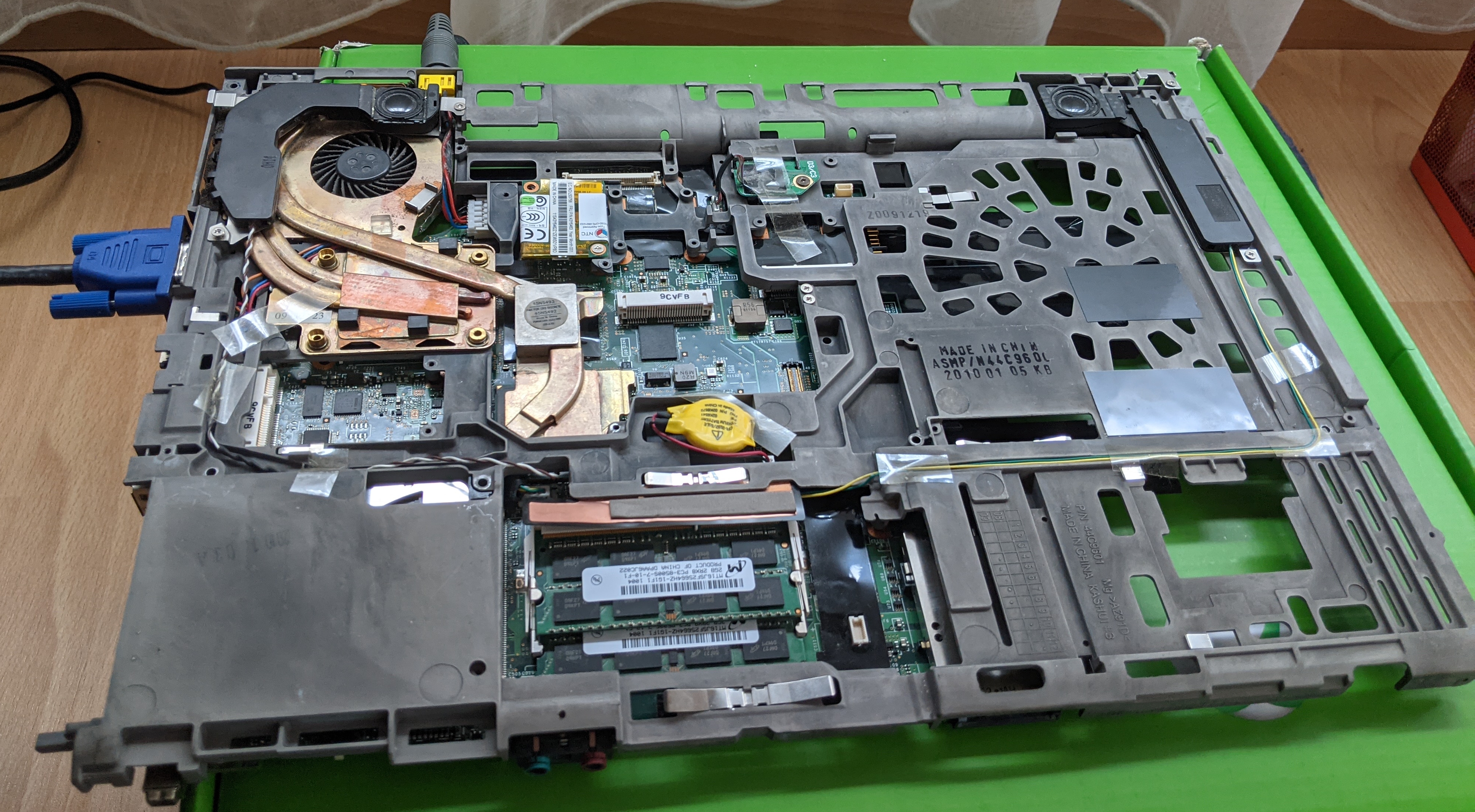
I didn’t fancy the idea of having to re-assemble before knowing if coreboot was going to work. The solution was to put together a minimal working version:
- Use only the main board and the big metalic, grey piece with the fan on it
- Connect the little cables corresponding to the fan, the CPU battery and the power
- Insert the RAM modules in their place
- Connect an external display via VGA port
- Do NOT put any screws in place yet
- Do NOT connect the hard disk
The result: after powering on the “machine”, following nice words greeted me on the screen:
SeaBIOS (version rel/1.14.0-0-g155821a)
Machine UUID df574981-504b-11cb-9973-fe56060fbf6e

Press ESC for boot menu.

Booting from Floppy...
Boot failed: could not read the boot disk

Booting from Hard Disk...
Boot failed: could not read the boot disk

No bootable device. Retrying in 60 seconds.
Those were good news! The coreboot image with the seabios payload were working correctly.
I went then a little bit further:
- Connect the Live Ubuntu USB drive (the same one used at the beginning)
- Connect an USB keyboard
USB was working, so I was able to use the keyboard to select and boot Ubuntu from the external drive. However after a warning indicating critical temperature reached I shutted down again. To keep the temperature down, the thermal grease which was misplaced during disassembling had to be replaced. I ordered a tube of the grease.
To replace the grease, the fun must be disassembled:
- Remove the fan and clean it well
- Replace the thermal grease where necessary
- Re-attach the fan to the big grey piece
- Re-attach the mainboard to the big grey piece, this time putting all necessary screws back in place
- Connect the external display via VGA
- Connect an USB keyboard and the Live Ubuntu USB Drive
- Connect a mobile phone and activate USB Tethering to share the internet connection
NOTE: how convenient that the Thinkwpad W500 has THREE usb ports :)
Boot from the external drive. This time there was no temperature warning, so the thermal grease was doing its job properly. Download and build flashrom from source (as described in 1.3. Use Flashrom internally).
Run flashrom with the internal programmer:
ubuntu@ubuntu:~$ sudo flashrom -p internal
flashrom v1.2-292-gb81dbc5 on Linux 5.4.0-42-generic (x86_64)
flashrom is free software, get the source code at https://flashrom.org

Using clock_gettime for delay loops (clk_id: 1, resolution: 1ns).
coreboot table found at 0x7d76e000.
Found chipset "Intel ICH9M".
Enabling flash write... OK.
Found Macronix flash chip "MX25L3205(A)" (4096 kB, SPI) mapped at physical address 0x00000000ffc00000.
Found Macronix flash chip "MX25L3205D/MX25L3208D" (4096 kB, SPI) mapped at physical address 0x00000000ffc00000.
Found Macronix flash chip "MX25L3206E/MX25L3208E" (4096 kB, SPI) mapped at physical address 0x00000000ffc00000.
Found Macronix flash chip "MX25L3233F/MX25L3273E" (4096 kB, SPI) mapped at physical address 0x00000000ffc00000.
Multiple flash chip definitions match the detected chip(s): "MX25L3205(A)", "MX25L3205D/MX25L3208D", "MX25L3206E/MX25L3208E", "MX25L3233F/MX25L3273E"
Please specify which chip definition to use with the -c <chipname> option.
Comparing this output with the first one at the beginning of this post, we see the write protection is gone. From now one, we’ll be able to flash a complete image to the chip without disassembling.
After this last test, it was time to sit down and patiently bring the laptop back to life, with all its parts and tiny screws, knowing that the flashing had been succesful.
Boot the Live Ubuntu on the USB drive. Select Install Ubuntu and proceed with the installation.
And that’s it: a brand-new-old Thinkpad W500 featuring Coreboot, SeaBios and Ubuntu :D
A nice colateral effect of this whole exercise was that the overheating was gone - probably due to the cleaning of the fan and to the new thermal grease.
Mainboards supported by coreboot